Radiation from a Circular Baffled Piston
A circular piston in a large baffle is a good starting approximation for investigating the radiation of sound from a boxed loudspeaker, or the radiation of sound from the open end of a flanged-pipe.
The far-field pressure radiated by a baffled piston depends on the radius of the piston a, the frequency (through the wavenumber k and the direction θ  (with =0o being directly in front of the piston) according to
Low frequency (ka<1)
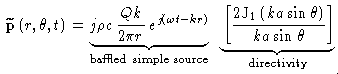
At low frequencies (when ka is small) a loudspeaker radiates sound equally well in all directions (a boxed loudspeaker will even radiate low frequency sound into the region behind the box). As shown in the animation below, sound waves radiating from the speaker spread out evenly in all directions. This behavior is primarily why the location of a subwoofer doesn't really matter - you can place it pretty much anywhere and it will still fill the room with sound.| Animation of sound field | Directivity pattern | 3-D directivity pattern |
|---|---|---|
 |  |  |
The color palette used to generate the Mathematica contour plots on this page was borrowed from
- V. W. Sparrow, J. L. Rochat, and B. A. Bard, "The use of color in the scientific visualization of acoustical phenomena," J. Comp. Acoust. 4(2), 202-223 (1996)
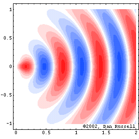
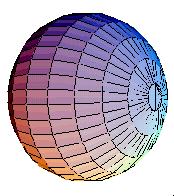
Medium frequency (ka>1)
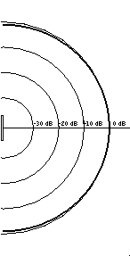
As the frequency gets higher, but assuming the speaker diameter does not change, the value of ka increases and the speaker becomes directional. That is, the sound energy produced by the speaker becomes channeled into a preferred direction and very little energy is radiated at other directions. In the animation below the radiated sound is pretty much contained within a cone of 55o from the center axis. Also, from the darkness of the contour shading (darker means higher pressure) you can see that the radiated sound field is strongest right in front of the speaker and weakens as you move to either side.| Animation of sound field | Directivity pattern | 3-D directivity pattern |
|---|---|---|
 |  |  |
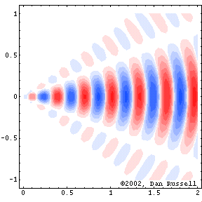
High frequency (ka>>1)
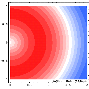
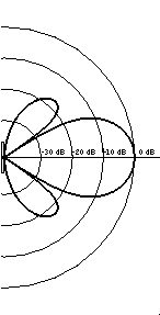
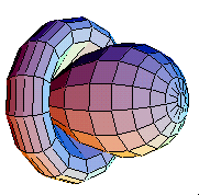
As the frequency becomes even higher (and ka becomes much bigger than 1) the sound field radiated by the speaker becomes even narrower and side lobes appear. Now the main lobe of radiated sound is limited to about 20o on either side of the central axis, and the pressure amplitude falls off rapidly as you move away from the central axis. Notice that the side lobes are much lower in amplitude than the main lobe (the darker the contour the higher the pressure - louder the sound). Also notice that the sound waves in the side lobes have the opposite phase as the sound wave in the main lobe.If you were using the same speaker (a large woofer) to produce both low and high frequencies, you would definitely notice a severe drop-off in the loudness of the higher frequencies as you step away from in front of the speaker. Fortunately, well designed loudspeaker systems don't attempt to send all frequencies through the same speaker so you probably won't observe this problem.
| Animation of sound field | Directivity pattern | 3-D directivity pattern |
|---|---|---|
 |  |  |
Measured Data for a Real Loudspeaker
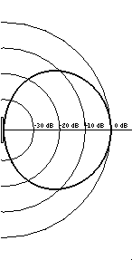
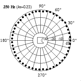 The animation at right shows actual directivity data measured for a 4-inch boxed loudspeaker.[1] At low frequencies (250 Hz) the speaker radiates sound equally well in all directions. At higher frequencies (10 kHz) the speaker radiates all of its sound in front - the sound level behind the speaker is almost 25 dB lower than the level in front, indicating that much more sound energy is being radiated directly in front and very little behind.
This tendency for a loudspeaker to become directional at higher frequencies is one of the main reasons for using a cross-over network when designing a multi-speaker system. The goal is to have each speaker in the system radiate sound with approximately the same spatial distribution over its own frequency range, so that the entire frequency output of the speaker (20-20,000 Hz) is radiated evenly into the listening space. The cross-over filter sends low frequencies (really small k) to the larger speaker (medium sized a) so that it is fairly omnidirectional (ka<5 is a typical upper limit). Likewise, mid-range frequencies (larger k) are sent to the mid-size speaker (smaller a) so that it has the same upper limit of directivity (ka<5). Finally, the highest frequencies (large k) are sent to the smallest speaker (really small a) so that it also has approximately the same spatial directivity (tiny speaker size ensures that ka is still < 5). The more omni-directional you want each speaker to be, the more different sized speakers you will need in order to cover the entire frequency range.[2] As an example, I have a set of Kenwood JL-840W 4-way speakers at home. The table below compares the speaker sizes and frequency ranges.
| Speaker | diameter (cm) | Frequencies (Hz) | cutoff ka |
|---|---|---|---|
| woofer | 30 | 20-2,000 | 5.5 |
| mid-range | 12 | 2,000-5,000 | 5.5 |
| tweeter | 6 | 5,000-10,000 | 5.5 |
| super-tweeter | 3 | 10,000-20,000 | 5.5 |
[1] D.A. Russell, J.P. Titlow, Y.J Bemmen., "Acoustic monopoles, dipoles, and quadrupoles: An experiment revisited," Am. J. Phys.,. 67(8), 660-664 (1999)
[2]There are lots of other arrangements of speakers which can produce nearly omni-directional sound over the entire frequency range. I'm using the example of a speaker system with several different sized speakers, each with its own crossover network, in order to demonstrate the effect of directivity on loudspeaker performance.
Back to Acoustics and Vibration Animations