Driving Room Modes: Source Location
All rooms (a cavity volume enclosed by boundaries) has resonant frequencies at which the acoustic response to a source can be extremely large. The frequencies at which resonances occur depend on the shape and dimensions of the room. At a resonance frequency the response of the room will be divided into antinodes, where the pressure is maximum, and nodes, where the pressure is zero. In a room with hard walls, the pressure will always be maximum at the wall or in a corner when the room is driven at any of its resonance frequencies. If the source is located at an antinode for a given resonance frequency, the room response will be greatest. If the source is located at a pressure node for a given resonance frequency, the room will not respond no matter how loud the source is.
Some audiofiles take advantage of their listening room's acoustic behavior to improve the performance of their stereo systems. Placing a loudspeaker or subwoofer against a wall or in the corner of a room allows the low frequency resonances of the room to enhance the low frequency performance of the loudspeakers. Sometimes the room is too responsive and the result is "boomy." Pulling the speakers out of the corners or away from the walls causes the room resonances to be driven less effectively resulting a flatter acoustic response.
The question that comes up then is, exactly how does source placement affect the acoustic response of the room in which the source is placed? The animations below will help to address this question. At present these animations are somewhat crude models, but hopefully they get the main pont across. As time permits they will be expanded to be more realistic.
Resonance Frequences of a 1-D Room
In order to illustrate the effect of source location on room response, let's start with a simple one-dimensional model: a rigid walled tube of length L, which is closed at both ends with a rigid end caps. The rigid ends ensure that pressure reflects without a phase reversal, so that an incident and reflected pressure wave have the same phase at the wall and thus add together constructively to produce a maximum. The resonance frequencies for our 1-D room are given by
fn=n c / 2 L
where c is the speed of sound in the room and n is an integer (n=1,2,3,4,.....).
For example, if our room has a length of L=5m, then the resonance frequencies of the first five room modes are:
| n | fn |
|---|
| 1 | 34.3 |
| 2 | 68.6 |
| 3 | 102.9 |
| 4 | 137.2 |
| 5 | 171.5 |
Response of the 1-D Room as a function of Source Location
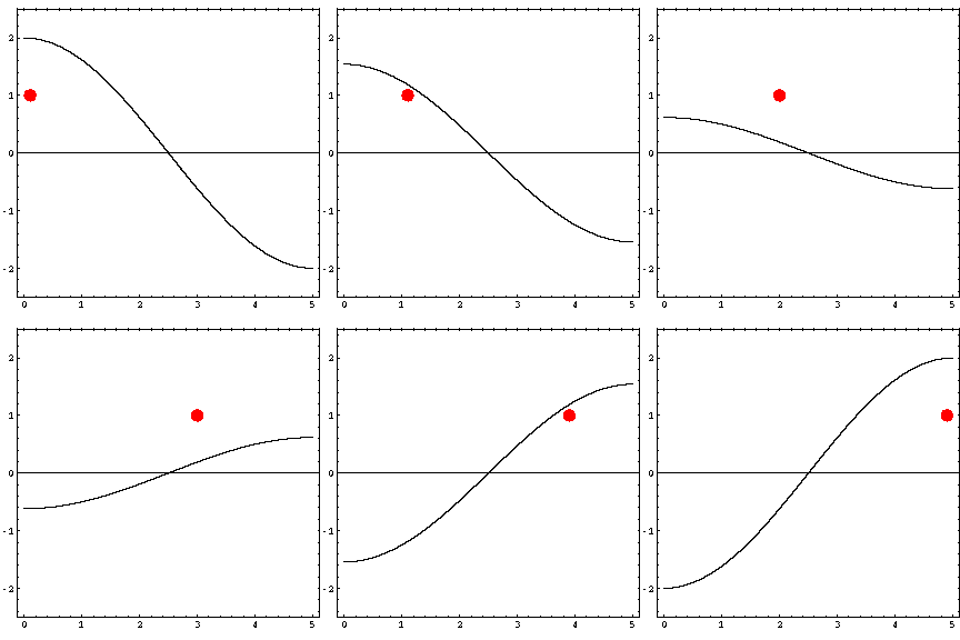
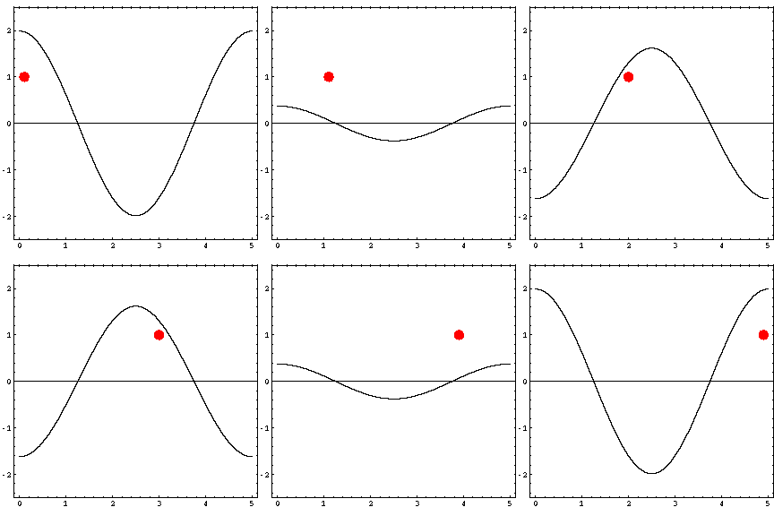
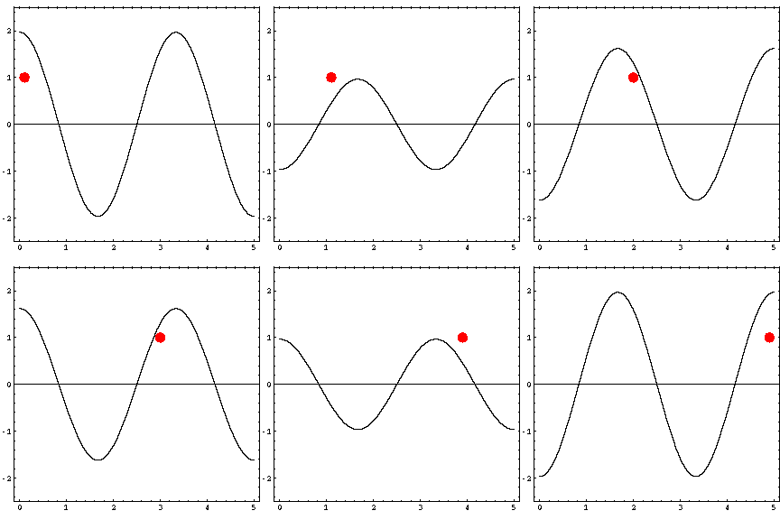
In the animations below, the red dot represents the source as it moves from the left wall (at x=0) towards the right wall (at x=5). The sine curve in the animation represents the amplitude of the pressure wave as a function of position in the room.
Driving the room at a resonance frequency
As the source moves along the length of the room, the resulting room response (as indicated by the amplitude of the pressure standing wave pattern) is a maximum when the source is located at an antinode for that given frequency. Notice that when the system is being driven at a resonance frequency the pressure amplitude is always greatest at the walls of the room. Furthermore, the maximum pressure is twice (2) the source amplitude, because the incident and reflected waves are in phase at the wall boundaries. When the source is placed at a node for that frequency standing wave pattern, the maximum room response drops to zero at that frequency. With a speaker located at a node, the room will be "dead" no matter how loud the speaker is. Moving the speaker a small distance away from the node brings back the room's response
| Mode 1 (34.3 Hz) | Mode 2 (68.6 Hz) | Mode 3 (102.9 Hz) |
 |
 |
 |
Further work (room for improvement)
- Most rooms have three dimensions (look at contour map of 2-D sound field)
- Sound level falls off with distance from source
- Absorption on walls can reduce reflection
Back to the Acoustics Animations Page


